Hey everyone, it’s Jake here, and if you’ve ever worked with PMDC motors (that’s Permanent Magnet DC motors, for anyone new to the space), you’ve probably run into the term “electrical time constant” before. Maybe you saw it on a spec sheet, or a design engineer asked you to calculate it for a custom project, and you were like… “Wait, what even is that again, and why does it matter so much?” Trust me, I’ve been there. Back when I first started out in the motor supply game, I’d skip over that number all the time—until a client came to me with a prototype that kept burning out drives, and it turned out I’d misjudged the time constant by a mile. Lesson learned. Now, I’m gonna break this down like I explain it to my interns, no overly complicated jargon, just real stuff that actually works when you’re working with our PMDC motors. Permanent Magnet DC Moto
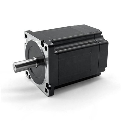
First, let’s get the basics out of the way. The electrical time constant (we usually just call it τ_e, pronounced “tau e” around the shop) is basically the speed at which the current in the motor’s windings reacts to changes in voltage. Think of it like this: when you flip a switch to power up a motor, the windings (which are just coils of copper wire) don’t just jump to full current instantly. It takes a tiny bit of time for current to build up, and τ_e is how long that takes. If you’re using a motor in a fast-paced application—like a robotic arm that needs to snap into position, or a power window motor that has to roll up in half a second—this number is non-negotiable. Get it wrong, and your control system might lag, or even blow your motor’s driver. That’s why every engineer worth their salt cares about this, and as a PMDC motor supplier, it’s one of the first questions I get when a client is spec’ing a new unit.
Now, let’s get to the actual math. I know, I know—math sounds scary, but stick with me. It’s super straightforward, and I’ll tie it back to our motors so it’s not just a random formula. The electrical time constant for a PMDC motor is calculated using two key values: the armature inductance (let’s call that L, measured in henries, or H for short) and the armature resistance (R, measured in ohms, Ω). The formula is just τ_e = L / R. That’s it. Two numbers, divide ’em, and you’ve got your time constant. Wait, that’s way simpler than I thought, right? But hold up—you can’t just grab any L or R, you need the right ones for the armature, which is the part of the motor that spins and carries current. No mixing up stator values or anything, that’s a common rookie mistake.
Let me break down what L and R actually are for our PMDC motors, because that’s where a lot of people go wrong with the calculation. Armature resistance R is the total electrical resistance of the copper windings in the armature, right? This changes a tiny bit with temperature—copper gets more resistant when it’s hot, so we usually use the rated 25°C value from the motor’s spec sheet for τ_e calculations, unless you’re working in extreme temp conditions, then you have to adjust it. For our standard PMDC motors, we test each unit’s R during manufacturing, so you can always find that number on the spec sheet we send out when you request a quote. No guessing there.
Then there’s armature inductance L. That’s the property of the windings that resists changes in current—so that’s what makes the current take time to build up, which is exactly what τ_e is measuring. Inductance for PMDC motors depends on how many turns of wire are in the armature, the size of the wire, and the gap between the armature and the permanent magnets (which are fixed in the stator of a PMDC motor, unlike brushed DC motors that might have field windings). Again, for our motors, we test L with an inductance meter, so it’s also on the spec sheet—no need to calculate L from scratch, which is a huge relief. If you’re using an off-the-shelf motor, that’s easy, but if you’re spec’ing a custom one, we can run the L and R tests before we finalize the design, so you don’t have to wait around.
Wait, let’s test this with an actual example from our shop, because that makes it real. Let’s say we have a standard 12V PMDC motor we supply for small automation tasks. Its spec sheet says armature resistance R is 0.5 Ω, and armature inductance L is 0.002 H. Plugging into the formula: τ_e = 0.002 / 0.5 = 0.004 seconds, or 4 milliseconds. That means it takes 4 milliseconds for the current to reach ~63% of its maximum value when we apply rated voltage. If you’ve got a motor that needs to respond in less than 10 ms, this one’s perfect. If you need something faster, we can tweak the winding design to lower L or R, which would bring τ_e down. For a comparison, a larger PMDC motor for conveyor systems might have R = 0.2 Ω, L = 0.01 H, so τ_e = 0.01 / 0.2 = 0.05 seconds, or 50 ms—slower, but that makes sense for a heavy load that doesn’t need to snap around fast.
But hold up—there’s a common mistake here: mixing up electrical time constant with mechanical time constant. That’s another number, τ_m, which is about how fast the motor’s shaft speed reacts, not current. New engineers especially mix these up, so let’s clarify that right now. τ_e is all about current rise time, τ_m is about speed. For our 12V example, τ_m would be a lot bigger—like, maybe 0.2 seconds or something, because it includes the motor’s inertia and torque. You don’t calculate τ_m with L and R, it uses Kt (torque constant) and J (inertia), so don’t plug those numbers into the τ_e formula. I can’t tell you how many times I’ve gotten an email from a client asking “wait, why is your time constant different from what I calculated?” and it’s because they mixed up e and m. Don’t do that, it’ll save you hours of headaches.
Another thing: why does this actually matter for your application? Let’s go back to that client I mentioned earlier, the one with the burning drives. They were using a small PMDC motor for a pick-and-place robot, and they calculated τ_e as 0.002 seconds, but they used the wrong R value—they used the terminal resistance instead of the armature resistance, which is about 10% higher because of the brushes. Wait, right! Brushed PMDC motors have brushes that make contact with the commutator, so there’s a small contact resistance in addition to the winding resistance. That’s not included in the armature R from the windings, so if you just measure the resistance between the two motor terminals with a multimeter, that’s the total terminal resistance, which is a tiny bit higher than the actual armature R we use for τ_e. That client used the multimeter reading, which was 0.55 Ω instead of our tested armature R of 0.5 Ω, so they calculated τ_e as 0.002 / 0.55 = ~0.0036 seconds, which was almost the same, but when they ran the robot at full speed, the current spiked because they didn’t account for the fact that τ_e tells you how much current is flowing at a given time. If your drive is tuned for a τ_e that’s lower than the real one, it’ll send too much current too fast, frying the drive or even the motor windings. That’s why using the tested values from the motor’s spec sheet is non-negotiable—we list both terminal resistance and armature resistance on all our spec sheets, so you can pick the right one for τ_e.
Also, if you’re designing a control system for your motor, the electrical time constant is a key factor in choosing the PWM (pulse-width modulation) frequency. PWM is what most motor drives use to control speed, right? They switch the voltage on and off really fast. If your PWM frequency is too close to 1/τ_e, you’ll get current ripple that causes extra heat and wears out the motor faster. For our 12V motor with τ_e = 4 ms, 1/τ_e is 250 Hz, so you’d want to run your PWM at least 5 times that, like 1-2 kHz, to keep the ripple low. We always include a recommendation for PWM frequency on our custom motor quotes, based on the τ_e we calculate for that specific unit, so you don’t have to guess. That’s the kind of value add we bring as a supplier—we don’t just sell motors, we give you the data you need to make your system work.
Wait, what if you don’t have the spec sheet? Maybe you have an old motor, or a prototype you’re testing, and you need to calculate τ_e without the L and R values. Is there a way to measure it, not just calculate it? Yeah, that’s a good question, and I get asked that a lot. The direct way is to hook up the motor to a power supply that can measure current, apply a step voltage (like jump from 0 to rated voltage instantly), and record the current over time. The current rise will follow an exponential curve: I(t) = I_max * (1 – e^(-t/τ_e)). So if you wait for t = τ_e, the current will be at ~63% of I_max, like I mentioned earlier. You can plot that current curve, find the time at which it hits 63% of max current, and that’s your τ_e. That’s super easy to do with an oscilloscope and a current probe—no fancy tools needed, just something that can track current over time. We do this test on every motor before it leaves our facility, so we’ve got that data for every unit we ship.
Another trick: if you know the motor’s no-load current and stalled current, can you get a rough estimate? Maybe, but it’s not as accurate. Stalled current is I_stall = V / R, so if you measure I_stall at rated voltage, you can get R = V / I_stall. Then L is a bit trickier—you’d need to calculate it from the motor’s back EMF constant, but that’s more involved and can throw off your τ_e if your back EMF constant is off. For most applications, using the tested L and R from the spec sheet is way more reliable than a rough estimate.
Now, let’s talk about when τ_e is a big deal, and when it’s less so. Like I said earlier, if you’re dealing with a high-speed, high-precision application—robotics, CNC, medical devices, things that need to move fast and accurately—τ_e is critical. If your motor’s τ_e is too high, the current doesn’t build up fast enough, so the motor can’t produce torque when you need it, leading to slow response times or missed positions. On the flip side, if you have a low-speed application, like a door opener or a fan that just needs to turn at a steady speed, τ_e matters way less. Those applications usually run at constant voltage, so the current stabilizes before you need to change anything. That’s why when a client comes to us for a fan motor, we don’t spend a ton of time tweaking τ_e, but for a robotic arm motor, that’s one of the first specs we discuss.
As a PMDC motor supplier, we pride ourselves on being transparent with this stuff. We don’t hide spec values, we explain what they mean, and we adjust designs to meet your τ_e needs if your application requires it. A lot of big suppliers just send you a spec sheet and say “good luck,” but we’re here to help. If you’re working on a new project and you need to calculate τ_e, or you’re not sure if the motor you’re using has the right τ_e for your system, just reach out. We can run the tests, adjust the winding design, or even give you a free consultation to make sure everything lines up. I’ve been doing this for 12 years, so I’ve seen every mistake in the book, and I’d rather help you avoid them than have you come back with a broken motor or drive.
Wait, let’s recap to make sure we didn’t miss anything. The electrical time constant for a PMDC motor is τ_e = L / R, where L is armature inductance (henries) and R is armature resistance (ohms). Use the tested values from the motor’s spec sheet, not terminal resistance, to get an accurate number. Don’t mix it up with the mechanical time constant. It’s critical for high-speed, high-precision applications, and it dictates the PWM frequency for your drive. If you need help calculating it, or you’re looking for a PMDC motor that meets your specific τ_e requirements, we’re here to make it easy.
At the end of the day, this stuff isn’t rocket science, but it’s the difference between a motor that works perfectly in your system and one that causes you headaches for weeks. I’ve spent too many nights troubleshooting drives that blew up because someone messed up τ_e, so trust me when I say getting this right pays off. If you’re working on a new project, or you need to replace an old motor, or you just have questions about time constants or any other motor spec, don’t hesitate to get in touch. We’ll walk you through every step, no jargon, no runaround, just real answers and the right motor for your needs.
And that’s it for today—next time you see τ_e on a spec sheet, you’ll know exactly what it means and how to use it. Hit us up anytime, we’re here to help.
DC Motor References
- Electrical Machines, Drives, and Power Systems, T. Wildi
- Permanent Magnet DC Motor Design and Application Guide, Electric Power Research Institute
- PMDC Motor Performance Specifications: A Practical Overview, Motion Control Magazine
- Industrial Motor Control, S. Herman
Zibo Auric Mechanical and Electrical Technology Co., Ltd.
As one of the leading permanent magnet dc moto manufacturers and suppliers in China, we warmly welcome you to buy advanced permanent magnet dc moto for sale here from our factory. All customized motors are with high quality and competitive price.
Address: B419, High-tech Entrepreneurship Park, High-tech Zone, Zibo City
E-mail: cui@auricmotor.com
WebSite: https://www.auricmotor.com/
